Search This Blog

Wednesday, October 21, 2015

CNC MACHINING CENTERS


                    The machining centre is a machine tool which is capable of doing multiple machining operations on a work part in a single setup. Recent CNC machining centers are equipped with lot of feature which can increase the production and time saving. Time saving on CNC is a huge profit for the company.
The machining center designation refers to the orientation of the machine spindle, and is classified as below:

  1. Vertical Machining centers (VMC).
  2. Horizontal Machining centers (HMC).
  3. Universal Machining centers (UMC).


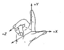
  1. Vertical machining centre (VMC):


These machines have its spindle on a vertical axis relative to the work table and always perpendicular to the machining bed. A vertical machining centre (VMC) is typically used for flat work that requires tool access from top. E.g. mould and die cavities, large components of aircraft. Vertical machining centers are limited for the small type of components. These machines are less expensive compared to the other machining centers.

Axes Designation in vertical machining centers is as shown below:

    2. Horizontal machining centre (HMC):


This type of machines have the Z axis in the horizontal position and the part is loaded on the table vertically in X and Y direction. Horizontal machining centers are used for machining the cube shaped parts where tool access can be best achieved on the sides of the cube. The number of setups can be reduced compared to the Vertical machining centers.  Some horizontal machining centers have their bed in X and Y axis perpendicular to the spindle and some have in X and Z axis parallel to the spindle.
Axes Designation in vertical machining centers is as shown below:


               3.  Universal machining centre (UMC):

These machines are the machines which has 5 or more axis. It has a work head that swivels its spindle axis to any angle between horizontal and vertical making this a very flexible machine tool.  The complex parts like Aerofoil shapes, curvilinear geometries can be machined using these universal machining centers. These machines works on the swivels spindle axis which is called pivot point. Most of these machines are used for finishing of parts due to achieving of high accuracy. 

Advantages of machining centers:

·         Reduced setups which gains the time and saves the machining cost.
·         Reduced part handling by the operator, due to reduced setups.
·         The parts utilize the same fixture throughout their processing which Increases the accuracy and repeatability.
·         Faster process and faster delivery of parts in small lot sizes.

Disadvantages of machining centers:

·         These machines are more expensive compared to other conventional machines.
·         Need highly skilled and trained labors to operate these machines.
·         Needs software’s for DNC, Simulation and CAM programming, which makes the cost higher to use these machines.

Features of CNC machining centers:

Usually the CNC machining centers are designed with many features to reduce non productive time. Some of the features are:

                      1.       Automatic tool changer (ATC).
                2.       Automatic work part positioned.
                3.       Automatic pallet changer.


       1.       Automatic tool changer (ATC):

                        The Cutting tools are stored in the storage unit called the “tool magazine” which is integrated with the machine tool and named with the tool numbers. When a tool number is called by the tool number the magazine rotates to the proper position and an automatic tool changer (ATC) with the program control, exchanges the tool in the spindle for the tool in the tool storage unit. The Capacities of tool magazine commonly range from 16 to 80 cutting tools. These Automatic tool changes save the manual tool changing and the big save on the cycle time or the operation time.

      2.       Automatic work part positioned:

                      Automatic work part positioning acts as rotary axis rotating the part and give access to the cutting to machine, many horizontal and vertical machining centers have the capability to orient the work part relative to the spindle. The table can be oriented at any angle about a vertical axis to permit the cutting tool to access almost the entire surface of the part in a single setup. These automatic work part positions are programmed by the programmer. The positioning of the rotation is very important the tool need to move to safety plane when there is a big rotation in the rapid. With these features we can reduce the number of setups and save huge time and gain increase in productivity.

       3.       Automatic pallet changer:

                    Recent modern Machining centers are equipped with two (or more) separate pallets that can be changed using an automatic pallet changer. While machining is performed with one pallet in position at the machine, the other pallet is in a safe location out of the machine. The operator can unload the finished part and then fixture the raw work part for next cycle with the pallet outside the machine. Using these automatic pallet changers the time of loading and unloading the part can be saved and the machine will be loaded continuously. These featured machines are very helpful in mass production activity.

Enjoy learning CNC Programming.

Monday, October 19, 2015

Classification of CNC control systems


            The CNC control systems can be classified based on below types:

1.      Motion type CNC

1.1.   Contouring systems
1.2.   Point to point systems

2.      Control  loop CNC

2.1.   Closed loop system
2.2.   Open loop system

3.      Number of axis type CNC

3.1.   2-axis machines
3.2.   2.5 axis machines
3.3.   3 axis machines
3.4.   4 axis machines
3.5.   5 axis machines and above.

1.     Motion type CNC Control:

            Based on the basic difference of the machine to be controlled there are two types of machine tools and control system. “Contouring systems” and “Point to point control system”.

1.1   Contouring system:

This type of machine tools works in a continuous path by cutting the material and following a contour of the part.  These machine tools are known as contouring machines which includes Milling, lathe and routing machines. These contouring machines are also capable of doing the work same as point to point system. These contouring system machines require simulations movement of the tool and the work piece i.e., the positions of the work piece and the tool are simultaneously controlled by a control system. These machines are uneconomical if it’s used as only point to control without continuous motions.  The contouring motion works as below shown in figure.

1.2   Point to point control system:

The work piece and the tool are placed in the position and the tool does its work. These types of machines are called point to point systems.  The drilling, tapping and boring machines are characterized under these types. The work piece is not moved until the tool finishes the job and retracts to the safety.  The point to point control system works as shown in the below figure.


2.     Loop control CNC systems:

Based on the looping system the CNC systems are classified into two categories, “Open loop system” and “closed loop system”.

2.1   Closed Loop system:

Since this type of system has feedback from the control system to the actual and the programmed input we call it as closed loop system. The CNC systems works on servo mechanism and it’s a closed loop principle. The feedback can be measured by analog or the digital systems. The analog systems measure the physical variables such as position and velocity in terms of voltage levels and digital systems monitor by electrical pulses.  These closed loop systems are accurate and powerful because of their capability of monitoring operational condition through feedback systems and automatically adjusting the variations in real time.

2.2   Open Loop system:

Open loop system are the systems in which instructions of program are sent into the controller through the input device and then these instructions are converted to the signals by the controller and sent to the servo amplifiers to energize the servo motors. The open loop systems are usually used in the point to point control systems where the accuracy doesn’t matter much and in few continuous path control system since there is no feedback from the system the result may deviate from the actual.

3.     Number of axis type CNC Control:


3.1   Two axis control system:

Two axis control system is a machine which give access to only two axis. The best example is the lathe machine.  The machine driven with the servo motor allows you only 2 axis, i.e., X and the z Axis.  Here in lathe the job will be rotating and the tool will be moving in 2 directions, indicating the depth Z and the cut in X direction.  So the program is done with x and the Z direction, where as in lathe universally use U and V which is implies same as X and Y.

3.2   Two and half axis control system:

Two and half axis control system  is also a three axis machine but the movement will not be 3 dimensional. These are the best example for drilling and tapping machines. First the X and the Y axis are moved to the position and then the third axis comes to effect.  In some of the machines the first X movement is made and the Y movement to reach the XY destination when it is in rapid, But while in feed or machining mode it does its work with 2 dimensional moving along x and y simultaneously, These type of machines may also called as two and half axis machines or 2.5 axis machine.

3.3   Three axis control system:

Three axis control systems are the machines which moves in three dimensional i.e., X, Y and Z axis move simultaneously. These are the most popular machines which can produce high accurate precision parts with three axis machines. The servo motor control the movements as per the instructions are given.  The three axis has verity of machines based on their bed lengths.  As the bed length increases the cost of the machine increases.  The number of setups increases and the cost also increases, three axis machines are limited for simple jobs and straight forward 3 axis jobs.

3.4   Four axis control system:

In Four axis control system is a three axis machine with an extra rotation on B-axis, four axis can be a vertical machine or an horizontal machine.
In vertical CNC machine the rotary head is added on the side of the machine bed. The machine works as the three axis machine but it has a rotary head for example if the holes have be machined on the tube, the tube can be mounted on the rotary B-axis and the drilling in the required angle. But vertical 4-axis machines are limited for the small jobs.
Horizontal 4-axis machines are used worldwide for successful machining of big parts in a single setup, where it takes 2-3 setups in a 3-axis machine. The part is mounted on the bed which has 360 rotations around Y direction i.e., B-Axis giving chance for the tool to cut on the angled faces in a single setup.

3.5   Five axis control system:

Five axis control system are the three axis machines with an extra rotation along Y and Z directions which are called B-axis and A-axis. As in Four axis machines B rotation is given by the bed and the A-axis rotation is given by the spindle movement called PIVOT point.  Using a five axis machine reduces the cycle time by machining the complex parts in a single setup and improves the accuracy on the positional errors by eliminating the setups.
                Five axis machining gives improved access to the under cuts and deep pockets by tilting the tool and also gives good surface finish and the tool life by tilting the tool to maintain optimum tool to part contact all the times.  

There are more than five axis control systems in the world making aerospace and automobile industries to achieve their accuracy and meet the requirements. 


Tuesday, October 13, 2015

Postprocessor Statements aptcodes

                        Statements that refer to the operation of the machine rather than to the geometry of the part or the motion of the cutter about the part are called postprocessor statements. APT postprocessor statements have been standardized internationally.Some common statements and an explanation of their meaning follow:

SEQNO/N,incr,k,m ==> This command controls the output sequence line number of the NC programs, Where as N is the initial sequence number, k is the increment desired, if sequence numbers are on desired at rapid motions then m=0, if sequence numbers are desired in all blocks then m=1.   

SEQNO/OFF ==> This command terminates or turn off the sequence number output in the program.

PARTNO/ ==>  This command identify the Program Number given to the Number, Most of the Program number start with the Letter O in the output NC program. 
Example: PARTNO/100 Apt code gives the output of O100 in NC program which defines the program number. 

PPRINT/ ==> This command is called postprocessor print, The character following the command will be printed in the post processor output. the maximum number of characters used can be 66. 
For example: if you want to operator to check the diameter of the hole at M00 you can print a message after M0 as PPRINT/(Check the hole diameter 10mm) ; and your program will appear ad below.
N00001 M00;
N00002 (Check the hole diameter 10mm) ;

MACHIN/ ==> Specifies the postprocessor that is to be used. Every postprocessor has an identity code, and this code must follow the slash mark (/). For example: MACHIN/Fanuc

TOOLNO/ ==> Specifies the tool parameters use in the post processor, define the diameter and the length of the tool used in the programming. 
for example: TOOLNO/100,MILL,10,0,50. Where as 10 is the diameter of the tool, 0 is the radius of the tool and 50 is the length of the tool.

SPINDL/ ==> Refers to spindle speed. If in revolutions per minute (rpm), only the number needbe shown. If in surface feet per minute (sfm), the letters SFM need to be shown, for example:SPINDL/ 100SFM. this command gives the output gcode M03. and SPINDL/OFF gives the output of M05.

LOADTL/ ==> Describes which tool to be loaded to the spindle, the tool magazine as several number of tool with the numbers, this command calls the tool number which is loaded in the magazine. 
Example: LOADTL/12, Calls the tool number 12 and loads into the spindle in case of automatic tool changer. this command gives the output gcode T12 M06

FEDRATE/ ==> Denotes the feed rate. If in inches per minute (ipm), only the number need be shown. If in inches per revolution (ipr), IPR must be shown, for example: FEDRAT/.005,IPR

COOLNT/ ==> This command defines the control of cutting fluid into the machine. 
Example: 
COOLNT/ON - this command gives the output gcode M07.
COOLNT/MIST -this command gives the output gcode M08.
COOLNT/FLOOD - this command gives the output gcode M18 ( Changes in some machine control)
COOLNT/OFF -this command gives the output gcode M09.

TURRET/  ==> Used to call for a selected tool or turret position

CYCLE/ ==> Specifies a cycle operation such as a drilling or boring cycle. An example of adrilling cycle is: CYCLE/DRILL,RAPTO,.45,FEDTO,0,IPR,.004. The next statement might be GOTO/PI and the drill will then move to P1 and perform the cycle operation. The cycle will repeat until the CYCLE/OFF statement is read.. 
CYCLE/DRILL - Drilling cycle, it gives the output of Gcode  G81.
CYCLE/REAM - Drilling cycle, it gives the output of Gcode  G85.
CYCLE/TAP - Drilling cycle, it gives the output of Gcode  G84.
CYCLE/OFF - Drilling cycle, it gives the output of Gcode  G80.


RAPID ==> Means rapid traverse and applies only to the statement that immediately follows it. this command gives the output gcode G00.

END ==> Stops the machine but does not turn off the control system, this command stops all the operations including the coolant, spindle and the machine. its like end of the program or operation. this command gives the Output of M02.

FINI ==> This command ends the programs and resets the program to the beginning of the program, it give the output of gcode M30  

STOP ==> This Command stops the program and let the operator to check the dimensions on the part, and cycle start to continue the program, it gives the out put of mcode M0.

OPSTOP==> This Command Halts the program Similar to STOP, and cycle start to continue the program, it gives the out put of mcode M1. to check the difference go to mcodes section.

INSERT ==> Inserts the command directly into the program, ignoring the postprocesser, use this command carefully, Example INSERT M01, it gives the out put of mcode M01 without calling OPSTOP command.

ORIGIN/ ==> This Apt command gives the origin defined by programmer, 
Example: ORIGIN/54, gives the out put of mcode G54.

FROM/X,Y,Z ==>  FROM Statement initializes the spindle start position from the coordinate system. if the FROM command not used the postprocesser will assume the start point coordinates are X0,Y0,Z0. most of the postprocesser developed gives the warning message for not using FROM command.

ROTABL/ATANGL ==> This command rotates the table at a specified defined angle. 
for example: ROTABL/ATANGL,45 in an 4axis horizontal table machine this command rotates the table at B45, it takes the shortest angle of rotation to reach B45 degrees it may be either clockwise or the anticlockwise.

ROTABL/INCR,45 ==> This command rotates the table 45 degrees incremental from its current position in clockwisse direction.

ROTABL/ATANGL,45,(A)(B)(C)AXIS ==> This command rotates the table 45 degrees in the specified axis either A or B or C as per the programmer commands.


There are several apt commands for the NC Programming, we will be updating one by one to cover all the code list. 

Enjoy learning CNC Programming and APT Programming.


Saturday, October 10, 2015

Motion Statements Apt programming

                  
So we have learnt how to define the Geometries from previous learning’s, now we can discuss how we can do the APT programming using the different geometries connecting each other and to give a motion to the tool to move forward continuously. APT motion statements are based on the concept that a milling cutter is guided by two surfaces when in a contouring mode.These surfaces are called the “part” and the “drive” surfaces are shown in below figure. Usually, the part surface guides the bottom of the cutter and the drive surface guides the side of the cutter. 


These surfaces may or may not be actual surfaces on the part, and although they may be imaginary to the part programmer. The cutter is either stopped or redirected by a third surface called a check surface. If one were to look directly down on these surfaces, 


The cutter can be stopped by giving an end point or a check surface. When cutter is moving towards to an end point or the check surface or it may move TO it, ONTO it, or PAST it, as illustrated in below figures.


When defining a continuous tool path statement after the cutter meets the check surface, it may go right denoted by the APT command GORGT, or go left, denoted by the command GOLFT as shown in the below figure. So this combination of the moving to check surface and then continuing left or right of the check surface to the next drive surface creates the continues tool paths.


In some cases the cutter may go forward, instructed by the command GOFWD, The command GOFWD is used when the cutter is moving either onto or off a tangent circular arc. These code instructions are part of what are called motion commands

Below figure shows the definition of the continues tool path and explained as below:


The cutter is moving along a drive surface, L1, toward a check surface, and stops to the line L2.
The APT motion statement for this move is: GOTO/L2,

When it arrives at L2, the cutter will make a right turn and move along L2 and past the new check surface L3. Note that L2 changes from a check surface to a drive surface the moment the cutter begins to move along it. The APT motion statement for this move is: GORGT/L2, PAST, L3

Then the cutter moves along L3 until it comes to L4. L3 now becomes new the drive surface and L4 becomes the check surface. The APT statement is:
GORGT/L3, TO, L4,

The cutter is moving to the right, it makes a left turn if one is looking in the direction of travel of the cutter. In writing the motion statements, the part programmers must imagine they are steering the cutter. The drive surface now becomes L4 and the check surface, C1. The APT statement is: GOLFT/L4, TANTO, and C1
This movement could continue indefinitely, with the cutter being guided by the drive, part, and check surfaces. The APT statement is: GOFWD/C1, TANTO, and L5.


Start-Up Statements:For the cutter to move along them, it must first be brought into contact with the three guiding surfaces by means of a start-up statement. There are three different start-up statements, depending on how many surfaces are involved.A three-surface start-up statement is one in which the cutter is moved to the drive, part,and check surfaces, as seen in below figure, 


A one-surface start-up is one in which the cutter is moved to the drive surface and the XY plane, where Z = 0, as in below figure


With the two- and one-surface start-up statements, the cutter moves in the most direct path, or perpendicular to the surfaces. Referring to (three-surface start-up), the move is initiated from a point P1. The two statements that will move the cutter from P1 to the three surfaces are:

GO/TO,DS,TO,PS,TO,CS

Five-Axis Machining: Machining on five axes is achieved by causing the APT program to generate automatically a unit vector that is normal to the surface being machined. The vector would be described by its X, Y, and Z components. These components,along with the X, Y, and Z coordinate positions of the tool tip, are fed into the postprocessor,which determines the locations and angles for the machine tool head and/or table.

Always the Apt programs may be different, but when the apt program is posted using postprocessor, the the standard Gcode will be generated, only the mcode will be machine dependent.

Enjoy learning Cnc programming and Apt programming.


Friday, October 09, 2015

Defining a Plane in an APT programming:

                            In an apt programming defining a plane in a space can be done by several methods, The apt programming for defining a plane is explained in this blog. the Gcode associated with the planes are G17, G18 and G19 which represents the XY, YZ and the ZX  planar coordinates. Intersection of these XY,YZ and ZX Planes passing through a point is called origin.
                           Planes are used in the CNC programming for defining a bottom of a part or used as a part surface or to define a safety approach and retract of the cutting tool. In CNC programming software's like CATIA V4, the Plane creation plays a major role for selecting the part surface.

Plane by three points in the space:
          Any three point in space can be joined to form a plane, for example, its like placing a plate on the three hinge points which keeps the plate without falling down. with one point and two hinge points we cannot balance a plate, so thus minimum 3 points are mandatory to create the plane.


Aptsource Code:
PL1=PLANE/P1,P2,P3


------------------------------------------------------------------------------------------------------------

Plane Parallel to other plane:
Plane can be created parallel to the another plane with the given distance. plane can be drawn parallel to XY, YZ or ZX plane at the origin. Also the plane can be drawn parallel to the planes created from the points, lines or the surfaces of the part. the Aptsource for the parallel plane can be written as shown below.


Aptsource Code:
PL1=PLANE/0,0,1,5 (0,0,1 is the I,J and K value)

PL2 may be defined as a plane parallel to PL1,

PL2=PLANE/PARALEL,PL1, ZLARGE, 10


------------------------------------------------------------------------------------------------------------
Similarly we can create a plane in the space in different methods, Creating a Plane by Two lines, creating a plane perpendicular to the other plane,
                            In CNC Programming the Planes are used in many ways, like selecting a bottom for toolpath, intersecting the part to know the sectional views of the part. the planes play a major role in defining the layers in the space. we can define 256 layers which uses the planes to define. the sketcher in an programming software work with the planes. when you select a plane in a sketcher then it becomes 2 dimensional with X, Y axis active in any Z level space.


enjoy learning Apt programming and cnc programming.


Thursday, October 08, 2015

Defining a Circle in an APT programming


In an Apt programming the geometry statement for defining a CIRCLE is very easy, as said before the APT programmer as kept everything close to English words.  The statement for circle can be written as C1 =CIRCLE/P1, R. So this command creates a Circle using a point and radius defined around it. . So when u are defining a CIRCLE command you must know the exact center point and the radius around it. The CIRCLE command is mainly used to the cutting material in the Circular motions or removing the material in the holes, the output gcode will be G02 for clockwise circular interpolation and the G03 for the anticlockwise interpolation. though the gcode is simple the background apt code will defer with respect to the arc or the circle.

Examples for the CIRCLE (C1) definition in APT programming:

There are many ways of defining the CIRCLE in an APT Programming, The following figures show the different ways of defining the CIRCLE in an APT programming


Center of the circle and the radius:
The circle can be drawn by knowing the center point and the radius of the circle. P1 is the center point from the X5 and Y6 from the origin point of the coordinates and R is the radius. this is the simple circle we draw commonly. 


Aptsource Code:
C1=CIRCLE/5,6,2
          OR
C1=CIRCLE/5,6,0,2 (Where 0=Z-axis)
          OR
C1=CIRCLE/CENTER,P1,RADIUS,2


----------------------------------------------------------------------------------------------------

Center of the circle and a tangent line:
The circle can be drawn by knowing the center point and using a line passing through tangent of the circle, here the center of the circle is fixed and the line is fixed, so the circle will be created using P1 as the center and the other end is joined to the tangent line to make the circle.


Aptsource Code:
C1=CIRCLE/CENTER,P1,TANTO,L1


----------------------------------------------------------------------------------------------------


Center of the circle and a point on the circumference:
The circle can be drawn by knowing the center point P1 and using another point P2 as the distance for the radius of the circle. In any space two point is enough to draw a circle. so the aptsource code can be written as shown as below, after drawing the circle the aptsource code takes the X and Y coordinates of P1 and P2 from the origin point and prepares the code.


Aptsource Code:
C1=CIRCLE/CENTER,P1,P2


----------------------------------------------------------------------------------------------------


Circle using three points:
The circle can be drawn by using the three points in a space, P1, P2 and P3 are the points in the space, so the curve moving the points makes a circle C1. however the aptsource code says the circle is formed using three points, the gcode generates the circle with the start point given and goes clock wise or anticlockwise to form a circle giving X,Y coordinate and I,J as the radius of the curve movement.


Aptsource Code:
C1=CIRCLE/P1, P2,P3


----------------------------------------------------------------------------------------------------


The center and a tangent circle:
The below drawing shows the two possibility of drawing a circle, If you have a point P1 and a circle C1, You can draw a circle C2 using point P1 as the center and the C1 circle circumference as tangent. Same way to draw a circle C3 you can use P1 as a center and the C2 circle circumference as tangent. the aptsource code can be written as shown.


Aptsource Code:
C1=CIRCLE/CENTER,P1,
SMALL,TANTO,C2
                OR
C3=CIRCLE/CENTER,P1,
LARGE,TANTO,C2


----------------------------------------------------------------------------------------------------


Center of the circle and a tangent to another circle:
If you have a center point P1, and Circle C2 in a space, you can draw a circle with two possibilities.
Circle C1 Can be drawn using center point P1 and the tangent to lower circumference of the Circle C2 and circle C3 can be drawn using center point P1 and the Tangent to the upper circumference of the circle. the aptsource code can be written to circle C1 and C3 is as shown below.


C1=CIRCLE/CENTER,P1,
SMALL,TANTO,C2
                OR
C3=CIRCLE/CENTER,P1,
LARGE,TANTO,C2


----------------------------------------------------------------------------------------------------


Known radius and the two intersecting lines:
The circle can be drawn by known radius and the two intersecting lines in the space, there are four corner while the line intersects, by using the known radius R we can draw circle tangent to each corners, we can draw for possible circles C1, C2, C3 and C4. the apt source for this code can be written a shown below,


Aptsource Code:
C1=CIRCLE/XLARGE,L2,
YSMALL,L1,RADIUS,.75
                  OR
C2=CIRCLE/XLARGE,L2,
YLARGE,L1,RADIUS,.75
                   OR
C3=CIRCLE/XSMALL,L2,
YLARGE,L1,RADIUS,.75
                    OR
C4=CIRCLE/XSMALL,L2,
YSMALL,L1,RADIUS,.75

The modifiers XLARGE, etc., are used to indicate which of the four circles is wanted.

----------------------------------------------------------------------------------------------------


Known radius and tangent to the line with the given radius:
If we have a known radius, a point and a tangent line in a space, the circles can be drawn in two possibilities. if the given point is P1, then the circle C1 and C2 can be drawn tangent to L1 passing through P1 in two possibilities as shown in below drawing. If the given point is P2 and it lies on the line, then the circle can be drawn in two possibilities as the circle passes through the point and the tangent to the line as shown in the below diagram. the aptsource for the circles C1,C2, C3 and C4 can be written as below: 


Aptsource Code:
C1=CIRCLE/TANTO,L1,
XSMALL,P1,RADIUS,.5
              OR
C2=CIRCLE/TANTO,L1,
XLARGE,P1,RADIUS,.5

If the point lies on the line then the apt program can be written as below,

C3=CIRCLE/TANTO,L1,
YLARGE,P2,RADIUS,.5
             OR
C4=CIRCLE/TANTO,L1,
YSMALL,P2,RADIUS,.5


----------------------------------------------------------------------------------------------------
I have explained some of the examples of drawing a circles, we can draw the circle in many ways in a space. now a days we you the computer software to calculate and generate the aptsource codes, computer software make the life easy. 

Enjoy learning cnc programming and Apt programming.