Search This Blog

Thursday, June 26, 2014

"What's G02-G03 G-code Circular interpolation"


G-C0de G02 and G03 Circular Interpolation.

IN CNC Programming G02 and G03 plays a major role for the circular tool movement along the planar axis.

G-CODE FORMAT:          

                                                N G02 X_ Y_ R_F;

                                                N G02 X_ Y_I_J_F;

                                                N G03 X_Y_R_F;

                                                N G03 X_ Y_I_J_F;

                Where as,

                        G02 - Clockwise circular cutting movement.

G03 - Anti-clockwise circular cutting movement.

X-Y_ - defines the arc end point in the work co-ordinate system.

R - Defines the length of the arc radius.

I_ J_ - Defines the distance of the arc start point from the centre point of the arc.

F_- Defines the feedrate along the arc movement.


Description:


·         The G-Code G02 Defines the clockwise circular cutting movement at a set feed rate.

·         The G-Code G03 Defines the Anti-clockwise circular cutting movement at a set feedrate.

·         I and J used in the program relates to the distance in X and the Y axis.

·         I relates to X Axis direction (+/-) from the start point of the arc to the arc centre as shown in below diagram.

·         J relates to Y Axis direction (+/-) from the start point of the arc to the arc centre as shown in below diagram.

·         The axis of the circle or helix must be parallel to the X-, Y- or Z-axis of the machine coordinate system


Note:

1.       When Programming arc using the Radius R the value of R must be equal or greater than the half longest distance along axis.
2.       I0 and J0 in any program lines can be omitted.
3.       G02 G-Code can be written in Two ways G02 or G2
4.        G03 G-Code can be written in Two ways G03 or G3

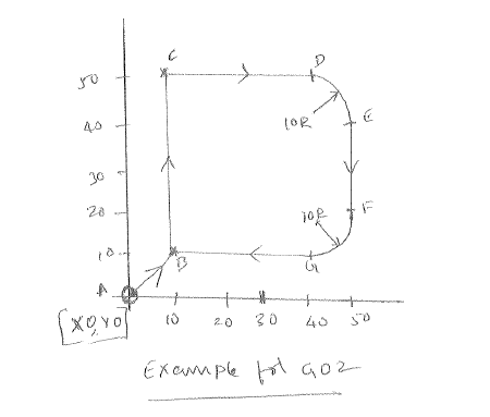
Example G02 Using I and J vectors:                          Example G02 Using Arc Radius:

G00 X0 Y0 Z50                                                                    G00 X0 Y0 Z50                    (POINT A)
G01 Z0 F50                                                                          G01 Z0 F50                         
X10 Y10                                                                                 X10 Y10                               (POINT B)
Y50                                                                                         Y50                                       (POINT C)
X40                                                                                         X40                                        (POINT D)
G02 X50 Y40 I0 J-10                                                          G02 X50 Y40 R10                 (POINT E)
G01 Y20                                                                                G01 Y20                                (POINT F)
G02 X40 Y10 I-10 J0                                                          G02 X40 Y10 R10                   (POINT G)
G01 X10                                                                                G01 X10                                (POINT B)

Example G03 Using I and J vectors:                          Example G02 Using Arc Radius:

G00 X0 Y0 Z50                                                                    G00 X0 Y0 Z50                    (POINT A)
G01 Z0 F50                                                                         G01 Z0 F50                         
G01 X10 Y10                                                                       G01 X10 Y10                   (POINT B)           
X40                                                                                       X40                                       (POINT C)
G03 X50 Y20 I0 J10                                                            G03 X50 Y20 R10               (POINT D)
G01 Y40                                                                                G01 Y40                              (POINT E)
G03 X40 Y50 I-10 J0                                                          G03 X40 Y50 R10               (POINT F)
G01 X10                                                                                G01 X10                              (POINT G)
Y10                                                                                         Y10                                      (POINT B)
If any query, please comment or contact me

Wednesday, June 11, 2014

How should be a CNC Programming structure ???


CNC Programming has a defined structure which machine can read the codes without errors. NC Programming can be categorized into 3 parts:

1.      Main Program.

2.      Part program.

3.      Sub program.

1.     Main Program Structure


The main program is first read or accessed on machine tool when the entire part program sequence is run. Normally, the controller operates according to one program. In this case the main program is also the part program. This controlling program can then call a number of smaller programs into operation. These smaller programs, called Sub Programs. These subprograms are generally used to perform repeat tasks, before returning control back to the main program.

Each block, or program line, contains addresses which appear in this order:

N, G, X, Y, Z, F, M, S, T;

This order should be maintained throughout every block in the program, although individual blocks may not necessarily contain all these addresses.


Meaning of addresses:

N          - Refers to the block number.

G          - Refers to the G code (Preparatory function).

X          - Refers to the distance travelled by the tool in the X axis direction.

Y          - Refers to the distance travelled by the tool in the Y axis direction.

Z          - Refers to the distance travelled by the tool in the Z axis direction.

F          - Refers to the feed rate.

M         - Refers to the M code (Miscellaneous function).

S          - Refers to the spindle speed.

T          - Refers to the tooling management.


2.      PART PROGRAM STRUCTURE


A part program is a list of coded instructions with series of letters and numbers. The part program includes all the geometrical and technological data to perform the required machine functions and movements to manufacture the part.

The part program can be further broken down into separate lines of data, each line describing a particular set of machining operations. These lines run in sequence, are called blocks. A block of data contains words which is called codes. Each word refers to a specific cutting/movement command or machine function. The programming language recognised by the CNC, the machine controller, is an I.S.O. code, which includes the G-Code and M-code groups. Each program word is composed from a letter, called the address, along with a number.


BLOCK EXAMPLE:  N010 G01 X50 Y100 F100


Word Example: G01


Address Example: G


The part program can contain a number of separate programs, which together describe all the operations required to manufacture the part.


3.      SUB PROGRAM STRUCTURE


In order to simplify the main Program in case of repeated patterns or fixed sequences the Sub program is called in between the main program. The Sub program always ends with M99 which indicates the end of sub program. Sub program can be called any number of times in a main program. When the main program calls one sub program into operation, the process is called a one-loop sub program call. It is possible to program a maximum four loop sub program call within the main program. Shown below is an illustration of a two-loop sub program call.  


Note:


1.      If cutter compensation is required on a tool and the co-ordinates for the tool are within the sub program, the cutter compensation must be applied and cancelled within the sub program.

2.      A sub program call command (M98 P1000) can be specified along with a move command in the same block. For example, G01 X63.2 M98 P1000;


Sub Program Repeat:


A call command can be set to call a sub program repeatedly. This call can specify up to 999 repetitions of a sub program. A sub program repeat command has the following format:

M98 P000 0000

When the repetition is omitted, the sub program will be called once only.

For example,

M98 P100001

This command is read call the sub program number 0001 ten times.