3.1 Entry and exit strategies:
These strategies ensure a gradual increase and decrease of the engagement angle as the cutting tool moves into and out of a cut. This decreases the shock on the tool and ensures smaller forces leading to an increased tool life. Implementing entry and exit strategies are good practice in all machining operations and are therefore applicable to all the strategies that will be discussed.
3.1.1 Down milling and up milling:
Down (or climb):
milling is characterized by a chip formation that starts out
with a high tensile stress as the cutter chips into the wall to form a thick
chip. The chip becomes thinner to the end of the cut until it is zero where the
cutting tool exits (Figure 1a). Up (or conventional) milling is characterized
by chip formation that starts out thin and becomes thicker as the cutter
approaches the edge where the deformed chip is sheared from the workpiece as in
Figure 1b. Up milling is likely to rub or burnish the workpiece at the starting
position of the chip and damage the surface where the chip is sheared off.
These can result in an unwanted surface finish and therefore down milling is
usually the more popular choice for titanium machining.

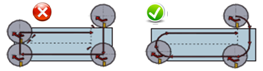
3.1.2 Rolling -in and –out:
Another strategy with which to control chip formation is illustrated in Figure 2 and is known as rolling into or out of a cut. To reduce shock and large forces on the cutting tool, this strategy ensures a gradual change in forces upon entry and exit. Having a gradual roll in process where chip formation starts out thick and gets thinner to the end of the cut as illustrated in Figure 2 (a) is better as opposed to a straight in process in (b). Rolling into the cut gives a better surface finish and an increased tool life as was discussed in section 3.1.1.
3.1.3 Ramp and interpolate:
This strategy does not require a starter hole and with the use of only one tool, simply ramps into the material and removes a thin layer at a time by interpolating along the cutting surface. After finishing one layer, the cutter tools ramp to the next layer and starts to remove material at that level [2]. There are two types of ramping operations that can be used: Linear ramping (two-axis ramping) or circular ramping (three-axis ramping) as shown in
Figure
3 (a) and (b) respectively.

3.2. Face Milling:
Face mills of normal design are used for milling relatively wide flat surfaces, usually wider than 5 inches. Diameters of face mills are important. They should be as wide as but not appreciably wider than the width of the cut. A good surface finish and freedom from distortion are desirable qualities when machining wide surface like sheets. Surface finish, in the case of milling, improves significantly with decreasing feed but only slightly with increasing speed.
•
Machined chips are thin, thus allowing a high feed
per tooth (fz), with low depth of cut, and therefore a very high vf work feed.
•
The dominant axial force is directed to the spindle
and stabilizes it.
•
This is of
great advantage with weak tool assemblies or long tools with a large overhang
because the risks of vibration are subsequently reduced.
•
Maximum cutting depth (ap max), is given by the
maximum angle of attack, the size of the cutting edge and the radius of the
insert (see sketch Below)
•
The angle of
attack varies depending on the geometry of the insert.
•
This maximum value is given in suppliers’ catalogs,
depending on the type of insert.

•
Never
exceed the maximum Ap, A value that depends on the type of insert, and is
always taken below the radius of the insert.

•
It is recommended that these tools stay permanently
engaged in the material for a better insert life, so avoid exits and re-entries
in/out of the material where possible.

3.3. End Milling:
End-milling cutters are used for facing, profiling, and end-milling operations; and include the standard end mills and two-lir3 end or slotting mills. Chip crowding, chip disposal, and tool deflection are possible problems in some end-milling operations. The proper combinations of hand of helix and hand of cut should be considered to avoid deflection of the cutter in the direction of an increasing depth of cut. Cutter diameter in profile or pocket milling depends on the radius needed on the pockets.
•
Always program HFM tools using radii in corners
within +/- 4% of the cutter diameter, before each change of direction or when
approaching a corner, to avoid having the real feed in the corner of the part,
and have a Hex (chip thickness) too high.
•
Reduce feedrate in corners (see TDB calculator)
•
Distance for reduced feed BEFORE the corner :
Rule
: Dia = 1 mm To Dia = 25 mm à
reduce 30% Dia of tool
Dia = 26 mm To Dia = 125 mm à
reduce 7,5 mm before corner
•
The
reduction after the corner can be > = 0


•
It is a milling method which can increase up to (3 x) the feed per tooth than conventional
machining methods

•
Hard materials (such as titanium), by always
maintaining a constant maximum ap
•
Due to greater axial loading, the cutting forces are
directed towards the machine spindle which means greater stability and reduced
vibration extending the life of the tool.
•
Cutting forces are at the bottom of the cutting edge profile
•
The depth of cut (ap max) is small - (dependant on
the type of insert), so you can significantly increase feedrates, to keep a
constant chip Thickness, and thus reduce machining time in some applications.
•
The HFM method takes advantage of the small depth of
cuts (ap). This gives a minimal radial force and maximum cutting force in the
axial (tool) direction, which reduces the risk of vibrations and machining is
more stable.
•
Because of this, you can considerably increase the
feedrate, thanks to of the low angle of attack, machining time for each part is
reduced, tool life is extended, and overall tool costs are lowered.
•
Not only the machining time is shorter for each part,
but the minimal radial cutting force also reduces wear on the spindle, whilst
the cutting forces are absorbed by the tool

There are essentially
three options for Roughing material out of a titanium pocket. They are: (1)
drilling and profile milling, (2) ramping to incremental depths, and (3)
drilling and plunge milling.
3.3.1. Drill and Profile Mill:
This approach begins with drilling a large-diameter starter hole in the pocket. For chip clearance, the drilled hole should be as large as possible, and at minimum, 1.3 or 1.4 times the diameter of the milling tool that will rough out the rest of the area. The rough milling cutter should then reach not quite as deep as the drilled hole leaving about 0.20 inch of stock in place for finishing the floor later (more on this below). Starting in the drilled hole, the milling cutter proceeds outward to mill the pocket depth in one set of passes. This approach also requires a stable process, meaning the pocket should be relatively shallow, and the tool overhang should be no greater than 4 times diameter.
3.3.2. Ramp and Interpolate:
This approach does not require a drilled hole. It uses just one tool. This is a milling cutter that ramps into the material and interpolates to machine one layer of the pocket before ramping to the next layer. Depths of cut are light, which may make this technique best for less-rigid machines such as some 40-taper machine tools. The technique can be used with a high-feed mill, but a milling cutter with circular inserts can ramp more aggressively. The approach can be much more effective than the previous technique for pockets that have varying depths resulting from a contoured shape.
3.3.3. Drill and Plunge:
Just
like the first technique, this one begins with a drilled hole. However, from
there, the machine essentially keeps on drilling—making overlapping plunges
with a plunge-milling tool or a drill capable of machining this way. The Z axis
is generally the stiffest axis of any machining center, so this technique can
allow pockets to be machined in titanium even on machines with poor rigidity.
It also offers an excellent way to machine deep pockets requiring tool
overhangs of 4 times diameter or more. Of course, one drawback of this
machining technique is the cusps that are left between plunging passes all
along the outline of the pocket. These have to be removed in a separate
operation.

3.3.4. Corner Concerns:
The first two techniques drill and profile mill, and ramp and interpolate share a common problem in the corners. Making a right-angle turn to machine an internal corner produces a dramatic increase in radial depth of cut. This can lead to excessive tool wear, tool breakage or unacceptable chatter marks in the corners not to mention an unpredictable process that is difficult to leave unattended. A drawing at right illustrates this. The constant-arc tool paths allow the process to maximize both chip load and radial depth of cut because the load on the tool remains steady throughout this spiraling path. The feed rate may change to allow for more abrupt changes in the toolpath direction as the cutter reaches the wall but even here, the tool should make large-diameter arcs that steer well clear of the internal corners. A technique that calls “slicing” which also could apply to the material left over in the corners after any of the three pocketing techniques described above.

3.3.5. Slicing:
When a cutting tool moves into a corner there is a dramatic increase in the radial depth of cut as shown in Figure 9. This increases the force on the cutting tool and will cause excessive wear or even tool breakage. A cutting strategy called slicing was developed to avoid this by keeping the load constant. With slicing, a series of increasingly shorter arcs are used with a light radial depth of cut to remove a small amount of material from the corner at a time. This keeps the engagement of the tool relatively constant while the corners are machined and thus will increase the tool life and efficiency of the machining process.

3.3.6. Finishing the Floor:
The final important consideration for getting material out of the pocket is the floor, which might be milled to its finish dimensions. Leaving 0.20 to 0.25 inch on the floor of the pocket is good practice in milling a titanium aircraft component. This amount of stock helps support the thin floor against vibration as the material is machined away. To ensure a stable cut, the floor of the pocket is machined to its finished depth in rings radiating out from the drilled hole.
3.3.7. Finishing thin walls (8:1 Rule):
8: 1 Rule proceeds in vertical stages, but also alternates between
roughing and finishing passes. The numbers here indicate the order in which the
regions of material would be removed to finish this rib. Areas roughed at a
large axial depth are followed by finishing passes taken at lighter axial
depths. The rib remains supported by the uncut material and emerges from the
stock as the areas are removed in this sequence.
When pocket walls are milled in a single pass at full depth, cutting
time is long and the thin wall is likely to vibrate. Machining in vertical
steps using the 8:1 rule is a faster and more stable way to finish the pocket.


3.3.8. Trochoidal Milling:
Trochoidal machining is a milling
process where the tool path continually re-crosses itself as the tool feeds
through an outline of constant radius arcs as illustrated in Figure 13. This makes
use of the advantages of circular milling and slicing so that the forces on the
tool are kept relatively constant. Trochoidal machining is therefore
appropriate to use in high speed machining (HSM) as the cutting tool always
moves along a curve with a constant radius and this also makes it possible to
maintain a relatively consistent feed rate throughout the machining process. Trochoidal machining can also be used in
3 dimensions (or axes) when moving from one layer to the next as illustrated in
Figure 14. The result of this tool path is that the tangency and curvature is
continuous at the starting and finishing points of each layer and therefore
yields better kinematic machine tool behavior.


3.4. DRILLING:
The unusual chip-formation
characteristics of titanium make drilling difficult. The thin chips flowing at
high velocities are likely to fold and clog in the flute3 of the drill. This
tendency, plus the high thrust pressures and confined nature of drilling,
produces high temperatures. A sharp drill produces tight curling chips without
difficulty. As the drill progressively dulls, the cutting temperature rises,
and titanium begins to smear on the lips and margins. The appearance of
feather-type chips in the flutes is a warning signal that the drill is dull and
should be replaced.
Drilling difficulties can be
minimized by employing five important techniques. These include:
·
Designing holes as
shallow as possible.
·
Using short, sharp
drills with large flutes and special points.
·
Flushing the tool-chip
contact site with suitable cutting fluids;
·
Employing low speeds
and positive feeds in a'- approved manner
·
Supplying solid support
under the exit side of through holes where burrs otherwise would form.
High-speed steels are generally
used for drilling titanium. Carbide drills can be used for deep holes when the
cost is justified.
Tool wear in Drills: Heat generation,
pressure, friction and stress distribution are the main contributors of drill
wear. The drill wear can be classified into: outer corner (w), flank
wear (Vb), margin wear (Mw), crater wear (KM), along with
two types of chisel edge wear (CT and CM) and chipping at the
cutting lips (PT and PM). Fig below shows the mentioned types of
wear.

3.5. Tapping and Threading:
Titanium
is difficult to tap. The problem of poor chip flow inherent in taps and the
severe galling action of titanium can result in poor threads, improper fits,
excessive tap seizures, and broken taps. Titanium also tends to shrink on the
tap at the completion of the cut.
Tapping
difficulties can be minimized by reducing the thread requirements to 55 to 65
per cent full thread” and then tapping the fewest threads that the design will
allow. Designers should also avoid specifying blind holes or through holes of
excessive lengths. In both cases, the chips are confined and can cause rough
threads and broken taps. Some relaxation in class-of-fit tolerances also should
be considered.
Tap Materials: Nitrided
high-speed steel taps are used: AISI-Ml for tapping commercially pure titanium
and AISI-MIO for titanium alloys.
If rubbing is encountered during
tapping, it may be decreased by:
·
Using interrupted
threads with alternate teeth missing.
·
Grinding away the
trailing edge of the tap
·
Grinding axial groves
in the thread crests along the full length of
lands
·
Employing either eccentric or concentric
thread relief.
3.6. Reaming:
Titanium can be
reamed with either straight or spiral fluted reamers. The conventional reamer
has three basic tool angles; a chamfer angle, a rake angle, and a relief angle as shown in Figure. The first
two angles do not have any pronounced effect on reaming operations. The relief
angle is most influential and should exceed 5 degrees, to minimize smearing. On
the other hand, relief angles in excess of 10 degrees cause vibration and
chatter marks on the surface of reamed holes.
