Search This Blog

Sunday, December 13, 2015

G89 Boring cycle


                                                    The Gcode G89 Boring canned cycle with dwell is used for boring and reaming operation. The G89 boring cycle is same as G85, but the difference between these two cycles is the G89 will use Dwell at bottom. Some times for boring operations, when the feedrate is required for the IN and the out directions of the machined hole, with a specified dwell at the bottom of the hole G89 is used.

Code line for G89 Boring cycle with dwell:


N100 G98 (G99) G89 X… Y… R… Z… P… F…

Diagram for G89 Boring cycle with dwell:


Steps for the G89 Boring cycle with dwell:

  • Rapid motion to XY position of the hole position.
  • Rapid motion to the R level, i.e., to the top of the hole position.
  • Feedrate motion to the depth in Z.
  • Dwell at the depth – in milli seconds (P).
  • Feedrate motion to Z depth.
  • Rapid retract to the initial level (with G98) or Rapid retract to R level (with G99).

G88 Boring cycle


                                                        The G88 boring is used rare, its use is limited to boring operations with special tools that requires manual interface at the bottom of the hole.  When this operation is completed, the tool is moved out of the hole for safety reasons. This cycle is used by some tool manufactures for certain operations.

Code line for G88 Boring cycle Spindle stop:


N100 G98 (G99) G88 X… Y… R… Z… P… F…


Diagram for G88 Boring cycle Spindle stop:


Steps for the G88 Boring cycle Spindle stop:


 1.       Rapid motion to XY position of the hole position.
       2.       Rapid motion to the R level, i.e., to the top of the hole position.
       3.       Feedrate motion to the depth in Z.
       4.       Dwell at the depth – in milli seconds (P).
       5.       Spindle rotation STOP (Feed hold condition is generated and the CNC operator switch's to manual operation mode and performs a manual task, then switches back to memory mode). CYCLE START will return to normal cycle.
        6.       Rapid retract to the initial level (with G98) or Rapid retract to R level (with G99).
        7.       Spindle rotation ON.

G87 Back Boring cycle


                                                            The G87 Back Boring cycle is a special cycle, its practical usage is limited due to the special tooling and setup requirements. Use the G87 Cycle only if the total costs can be justified economically. The boring bar must be set very carefully, it must be preset to match the diameter required for backboring, its cutting point must be set in the spindle oriented mode, facing the opposite direction than the shift direction.

Code line for G87 Back Boring cycle:


                There are two program formats available for the G87 back boring canned cycle. Unfortunately G99 is never used with the G87 cycle.

First one using the Q, which is commonly used:

N100 G98 G87 X… Y… R… Z… Q… F…

Second one using I and J:

N100 G98 G87 X… Y… R… Z… I… J… F…


Diagram for G87 Back Boring cycle:


Steps for the G87 Back Boring cycle:


 1.       Rapid motion to XY position of the hole position.
       2.       Spindle Rotation Stop.
       3.       Spindle Orientation.
       4.       Shift OUT (OSS) by the Q value or shift by the amount and direction of I and J.  
       5.       Rapid motion to the R level, i.e., to the bottom of the hole position.
       6.       Shift IN (OSS)by the Q value or shift back in the opposite direction of I and J. 
       7.       Spindle rotation ON (M03).
       8.       Feedrate motion to the depth in Z.
       9.       Spindle rotation STOP.
      10.   Spindle orientation.
      11.   Shift OUT (OSS) by the Q value or shift by the amount and direction of I and J. 
      12.   Rapid motion to the Initial level, i.e., to the top of the hole position.
      13.   Shift (OSS) IN by the Q value or shift back in the opposite direction of I and J. 
      14.   Spindle rotation ON.

G76 Precision Boring cycle


                                            The G76 is a very use full cycle for high quality holes. Same as G87 there are two programming formats available for the precision boring canned cycle G76.

Code line for G76 Precision Boring cycle:


                There are two program formats available for the G76 back boring canned cycle.

First one using the Q, which is commonly used:

N100 G98 (G99) G76 X… Y… R… Z… P… Q… F…

Second one using I and J:

N100 G98 (G99) G76 X… Y… R… Z… P… Q… F…


Diagram for G76 Precision Boring cycle:


Steps for the G76 Precision cycle:


1.       Rapid motion to XY position of the hole position.
      2.       Rapid motion to the R level. I.e., to the top of the hole.
      3.       Feed motion in the Z till the end of the hole.
      4.       Dwell at depth – in Milliseconds (P)
      5.       Spindle Rotation Stop.
      6.       Spindle Orientation.
      7.       Shift OUT (OSS) by the Q value or shift by the amount and direction of I and J. 
      8.       Rapid motion to the R level, i.e., to the top of the hole position.
      9.       Spindle rotation ON (M03).
     10.   Rapid retract to the initial level (with G98) or Rapid retract to R level (with G99).

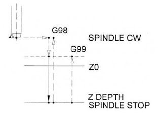
G86 Boring cycle


                                                          The G86 Boring cycle spindle stop Work similar to the G85 Boring cycle or the G81 Drilling cycle, But the difference is there will be no retract in the feedrate motion. In some cases Using G85 for boring tool may make the finish of the hole worse rather than improving because of removal of material in backward motion. In this G86 cycle the spindle is stopped as the depth of the hole is reached and the tool is retracted in rapid. This cycle is typically used for Roughing and semi finishing of the Holes.

Code line for G86 Boring cycle Spindle stop:


N100 G98 (G99) G86 X… Y… R… Z… F…

Diagram for G86 Boring cycle Spindle stop:


Steps for the G86 Boring cycle Spindle stop:


 1.       Rapid motion to XY position of the hole position.
       2.       Rapid motion to the R level, i.e., to the top of the hole position.
       3.       Feedrate motion to the depth in Z.
       4.       Spindle rotation STOP.
       5.       Rapid retract to the initial level (with G98) or Rapid retract to R level (with G99).

G85 Boring cycle


                                                   The G85 Boring cycle is used for boring and reaming operations. This cycle is used to improve the surface finish of the hole to meet the high dimension tolerance or the concentricity of the hole. This operation carries out the tool in and out of the hole without spindle stop. Point to be noted in this operation is a little amount of material will be removed during the tool is feeded backwards out of the hole, this happens because of the released tool pressure during retract.  This cycle is especially suitable for reaming.

Code line for G85 Boring cycle:


N100 G98 (G99) G85 X… Y… R… Z… F…

Diagram for G85 Boring cycle:


Steps for the G85 Boring cycle:


 1.       Rapid motion to XY position of the hole position.
       2.       Rapid motion to the R level, i.e., to the top of the hole position.
       3.       Feedrate motion to the depth in Z.
       4.       Feedrate motion back to the R level.
       5.       Rapid retract to the initial level (with G98) or Rapid retract to R level (with G99).
G74 Reverse Tapping cycle


                                        The G74 Gcode cycle is the standard reverse tapping cycle used for the Left hand thread in a hole. At the start of the cycle the Reverse spindle rotation M04 must be In effect.  The machine switches on the control panel cannot be accessed until the cycle of thread is completed. As said in G84 the spindle speed and the feed of the lead thread is very important, these relationship must be maintained at all the times of the tapping cycle.

Code line for G74 Tapping cycle:


N100 G98 (G99) G74 X… Y… R… Z… F…

Diagram for G74 Tapping cycle:

The cycle is the standard reverse tapping cycle used for the Left hand thread in a hole. At the start of the cycle the Reverse spindle rotation M04 must be In effect.  The machine switches on the control panel cannot be accessed until the cycle of thread is completed. As said in G84 the spindle speed and the feed of the lead thread is very important, these relationship must be maintained at all the times of the tapping cycle


Steps for the G74 Tapping cycle:

 1.       Rapid motion to XY position of the hole position.
       2.       Rapid motion to the R level, i.e., to the top of the hole position.
       3.       Feedrate motion to the depth of the thread in Z with CCW Spindle rotation (M04).
       4.       Spindle rotation stop in bottom of hole.
       5.       Spindle Clockwise rotation (M03) and back in feedrate to R level.
       6.       Spindle rotation Stop.
       7.       Spindle rotation Reverse (M04) and Rapid retract to the initial level (with G98) or Rapid retract to R            level (with G99).

Saturday, December 12, 2015

G84 Tapping cycle


                                        The G84 Gcode tapping cycle is the standard tapping cycle used for the right hand thread in a hole. At the start of the cycle the normal spindle rotation M03 must be In effect.  For tapping always R Level must be higher compared to the other cycles. The feedrate and the spindle speed calculation very important for the tapping cycle since there is a direct relationship between the spindle speed and the lead of the tap.

Code line for G84 Tapping cycle:


N100 G98 (G99) G84 X… Y… R… Z… F…

Diagram for G84 Tapping cycle:


Steps for the G84 Tapping cycle:


 1.       Rapid motion to XY position of the hole position.
       2.       Rapid motion to the R level, i.e., to the top of the hole position.
       3.       Feedrate motion to the depth of the thread in Z with Clockwise Spindle rotation (M03).
       4.       Spindle rotation stop in bottom of hole.
       5.       Spindle reverse rotation (M04) and back in feedrate to R level.
       6.       Spindle rotation Stop.
       7.       Spindle rotation normal (M03) and Rapid retract to the initial level (with G98) or Rapid retract to R              level (with G99).

G73 Chip break Drilling cycle


                                             The gcode G73 chip breaking cycle works same as deep hole drilling cycle G83and is also known as peck drilling cycle. But In this cycle the drill will not be retracted to the clearance position of the hole, the drill will retract only to specified height after drilling the certain depth of cut keeping the drill inside the hole. This cycle retracts to the specified height after each peck of drill and repeated until the total depth of the hole is achieved.
                The cycle G73 is used for the long series of the drills where we can expect the vibration of the tool and it can damage the hole and the tool. G73 cycle keeps the tool inside the hole until the drilling operation is completed and saving the time on the cycle.

Code line for G73 Chip break drilling cycle:


N100 G98 (G99) G73 X… Y… R… Z… Q… F…

Diagram for G73 Chip break drilling cycle:


Steps for the G73 Chip break drilling cycle:

 1.       Rapid motion to XY position of the hole position.
       2.       Rapid motion to the R level, i.e., to the top of the hole position.
       3.       Feedrate motion to the depth by the amount of Q value in Z.
       4.       Rapid retract to Clearance value Specified.
       5.       Feedrate motion in Z axis by the Q amount plus the clearance value.
       6.       Point number 4 and 5 repeated until the z depth of the hole is reached.
       7.       Rapid retract to the initial level (with G98) or Rapid retract to R level (with G99).

G83 Deep hole Drilling cycle


                        The deep hole drilling cycle (Standard Peck Drilling) is also known as peck drilling cycle. In this cycle the drill will be retracted to the clearance position of the hole after drilling the certain depth of cut. After retracting to clearance plane, this cycle retracts to the R level after each peck of drill and repeated until the total depth of the hole is achieved.

Code line for G83 Peck drilling cycle:


N100 G98 (G99) G83 X… Y… R… Z… Q… F…

Diagram for G83 peck Drilling cycle:


Steps for the G83 peck drilling cycle:


      1.       Rapid motion to XY position of the hole position.
      2.       Rapid motion to the R level, i.e., to the top of the hole position.
      3.       Feedrate motion to the depth by the amount of Q value in Z.
      4.       Rapid retract to R level.
      5.       Rapid motion to the previous drilled depth with clearance.
      6.       Point number 3, 4 and 5 repeated until the z depth of the hole is reached.
      7.       Rapid retract to the initial level (with G98) or Rapid retract to R level (with G99).

G82 Drilling cycle with dwell


                              The Gcode G82 Drilling cycle is work same as drilling cycle G81 but with dwell. Dwell is used for the some of the improve accuracy of the hole. During drilling with dwell the tool pauses at the hole bottom. These cycle is used for center drilling, spot drilling, spot facing, countersinking etc.

Code line for G82 Drilling cycle:


N100 G98 (G99) G82 X… Y… R… Z… P… F…

Diagram for G82 Drilling cycle with Dwell:


Steps for the G82 drilling cycle:


        1.       Rapid motion to XY position of the hole position.
        2.       Rapid motion to the R level, i.e., to the top of the hole position.
        3.       Feedrate motion to the depth of the hole in Z.
        4.       Dwell at the bottom of the hole. In milliseconds (P).
        5.       Rapid retract to the initial level (with G98) or Rapid retract to R level (with G99).

Friday, December 11, 2015

G81 Drilling cycle

                  The drilling cycle gcode G81 is canned cycle and is a simple drilling cycle used for drilling the hole without the dwell at the depth of the hole is not required. Mainly this cycle is used for the center drilling and the holes with small depth.

Code line for G81 Drilling cycle:


 N100 G98 (G99) G81 X... Y... R... Z... F...


Diagram for G81 Drilling cycle:


Steps for the G81 drilling cycle:


 1.       Rapid motion to the XY position of the hole position.
       2.       Rapid motion to the R level, i.e., to the top of the hole position.
       3.       Feedrate motion to the depth of the hole in Z
       4.       Rapid retract to the initial level (with G98) or Rapid retract to R level (with G99).